IP Transparency and Direct Server Return with NGINX and NGINX Plus as Transparent Proxy
table, th, td {
border: 1px solid black;
}
th {
background-color: #d3d3d3;
align: left;
padding-left: 5px;
padding-bottom: 2px;
padding-top: 2px;
line-height: 120%;
}
td {
padding-left: 5px;
padding-bottom: 5px;
padding-top: 5px;
line-height: 120%;
}
This blog post describes how to configure the open source NGINX software or NGINX Plus as a “transparent” proxy for traffic to upstream servers. It explains how you can use a transparent proxy to spoof the source IP address of packets to implement IP Transparency, and how you can implement a load‑balancing mode called Direct Server Return for UDP traffic.
The information in this post apply to both the open source NGINX software and NGINX Plus. For the sake of brevity, we’ll refer only to NGINX Plus.
Introducing Reverse Proxies
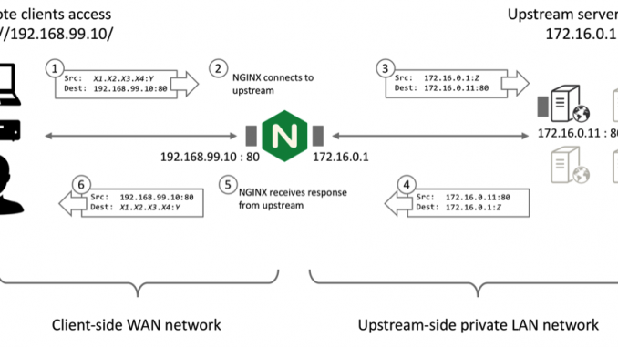
Unlike a switch or router that simply forwards packets, NGINX Plus operates as a standard reverse proxy. In this mode of operation, NGINX Plus manages separate client‑side and upstream‑side TCP connections (for HTTP and TCP traffic) or UDP sessions in order to control the communication between the remote client and the selected upstream server.
Remote clients make TCP connections directly to the NGINX Plus reverse proxy at its published IP address and port. NGINX Plus terminates the TCP connection and reads the request data within. NGINX Plus then makes a new TCP connection (or reuses an existing, idle connection) to the selected (load‑balanced) upstream server and writes the request data to the upstream server.
When NGINX Plus receives response data on the upstream connection, it writes the response data to the remote client using the client TCP connection. NGINX Plus may modify the response (for example, to apply compression to an HTTP response).
The UDP case is very similar: NGINX Plus receives UDP datagrams from remote clients and sends new datagrams to the selected (load‑balanced) upstream server. NGINX Plus holds its upstream socket open to receive responses from the upstream, which it sends back to the remote client.

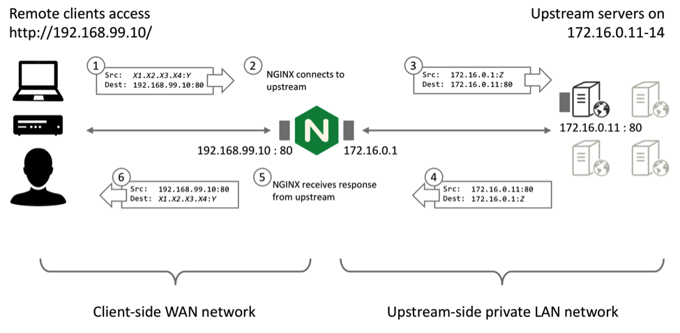
A consequence of this standard reverse proxy mode of operation is that the upstream server observes that TCP and UDP traffic originates from the local NGINX Plus proxy (Step 3 in the diagram above).
Benefits and Limitations of the Standard Reverse Proxy Mode
The standard reverse proxy mode of operation brings significant performance gains and efficiencies for HTTP and TCP traffic (including TCP optimizations, buffering, and HTTP keepalive reuse). It poses a challenge if the upstream server needs to determine the true origin IP address of the connection or session, for purposes such as authentication and access control, rate limiting, and logging, or other purposes.
For some protocols, NGINX Plus can use the X‑Forwarded‑For HTTP header or the PROXY protocol to provide the origin IP address to upstream servers. This post describes two additional methods, made possible by the transparent parameter to the proxy_bind directive, which was introduced in NGINX Plus Release 10 (R10):
- IP Transparency ensures that the upstream servers observe that each connection originates from the remote client that initiated it.
- Direct Server Return (DSR) further arranges that responses from the upstream servers go directly to the remote clients and bypass the intermediate load balancer.
It is complex to deploy and troubleshoot IP Transparency and DSR. Only implement these configurations if the standard reverse proxy mode of operation is not sufficient for your application or service.
IP Transparency
The intention of IP Transparency is to conceal the presence of the reverse proxy so that the origin server observes that the IP packets originate from the client’s IP address. IP Transparency can be used with TCP‑based and UDP‑based protocols.
Creating a Standard HTTP Reverse Proxy Service
To demonstrate IP Transparency, first create a load‑balanced cluster of four web servers that respond with some simple connection information.
-
Configure a simple HTTP virtual server that load balances traffic across a group of upstream servers:
# in the 'http' context
server {
listen 80;location / {
proxy_pass http://http_upstreams;
}
}upstream http_upstreams {
server 172.16.0.11;
server 172.16.0.12;
server 172.16.0.13;
server 172.16.0.14;
} -
To confirm that the upstream servers observe that the connections originate from the NGINX Plus load balancer, configure an NGINX Plus web server on each of the four of them (172.16.0.11 through 172.16.01.14) with a simple virtual server that returns information about the connection, such as:
# in the 'http' context
server {
listen 80;location / {
return 200 "Hello from $hostname. You connected from $remote_addr:$remote_port to $server_addr:$server_portn";
}
}
When we test this configuration, the upstreams report that the connections originate from the local NGINX Plus IP address (172.16.0.1):
$ for i in {1..4}; do curl http://192.168.99.10 ; done

Hello from dev1.  You connected from 172.16.0.1:42723 to 172.16.0.11:80

Hello from dev2.  You connected from 172.16.0.1:39117 to 172.16.0.12:80

Hello from dev3.  You connected from 172.16.0.1:54545 to 172.16.0.13:80

Hello from dev4.  You connected from 172.16.0.1:57020 to 172.16.0.14:80
Configuring NGINX Plus and Your Upstreams for IP Transparency
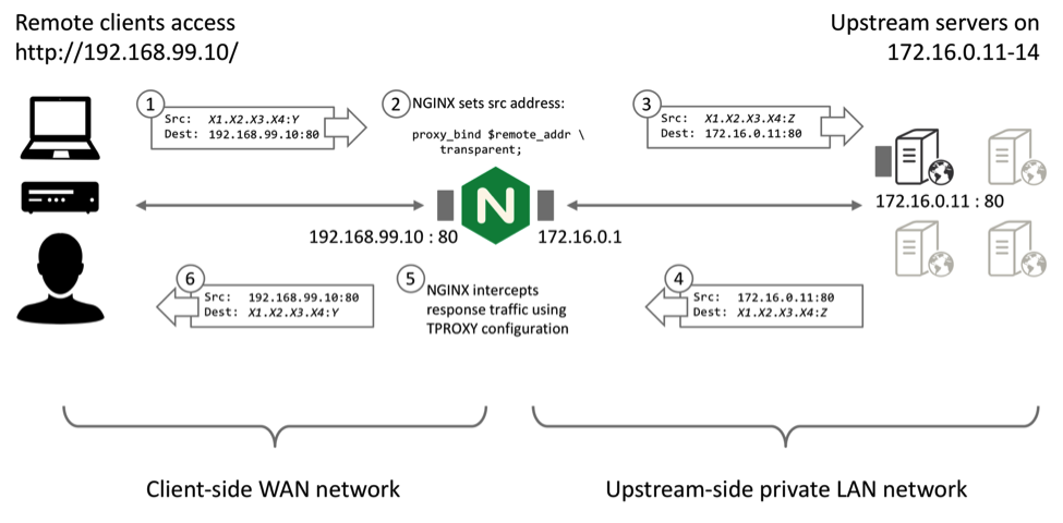
NGINX Plus R10 and later (and open source NGINX 1.11.0 and later can spoof the source address of upstream traffic. Include the transparent parameter to the proxy_bind directive. Most commonly, you set the source address to that of the remote client:
proxy_bind $remote_addr transparent;This simple step creates a significant challenge, however, because you need to ensure that response (egress) traffic to the remote client is correctly handled. The response traffic must be routed to the NGINX Plus reverse proxy, and NGINX Plus must terminate the TCP connection. NGINX Plus then sends the response traffic to the remote client using the client TCP connection:
The IP Transparency mode of operation uses the TPROXY kernel module, which is a standard feature of most modern Linux kernels. You need to make several configuration changes:
-
On the NGINX Plus server, configure the worker processes to run as root, so that they can bind upstream sockets to arbitrary addresses.
In the main (top-level) context in /etc/nginx/nginx.conf, include the
userdirective to set the NGINX Plus worker processes’ ID to root:# in the 'main' context
# user daemon is the default; use root with transparent proxy_bind
user root; -
On the NGINX Plus server, ensure that each connection originates from the remote client address (Step 2 in the diagram).
Add the
proxy_binddirective with thetransparentparameter to the configuration for the virtual server:# in the 'http' context
server {
listen 80;location / {
proxy_bind $remote_addr transparent;
proxy_pass http://http_upstreams;
}
} -
On the upstream servers, configure the routing so that all return traffic is forwarded to NGINX.
On each upstream server, configure the default route to be the IP address of the NGINX Plus reverse proxy. Note that this IP address must be on the same subnet as one of the upstream server’s interfaces.
# route add default gw 172.16.0.1Remove any pre‑existing default routes, and check that the routing table looks sensible:
# route del default gw 10.0.2.2

# route -n

Kernel IP routing table

Destination   Gateway     Genmask        Flags Metric Ref Use Iface

0.0.0.0       172.16.0.1  0.0.0.0        UG    0      0     0 eth2

10.0.2.0      0.0.0.0     255.255.255.0  U     0      0     0 eth0

172.16.0.0    0.0.0.0     255.255.255.0  U     0      0     0 eth2

192.168.56.0  0.0.0.0     255.255.255.0  U     0      0     0 eth1
If your upstream servers need to be able to connect to external servers, you need to configure the new NGINX Plus gateway to forward and masquerade traffic – see Enabling Upstreams to Reach External Servers below.
-
On the NGINX Plus server, configure the TPROXY kernel module to capture the return packets from the upstream servers and deliver them to NGINX Plus (Step 5 in the diagram).
In this example, we run the
iptablesandiprulecommands to capture all TCP traffic on port 80 from the servers represented by the IP range 172.16.0.0/28:# iptables -t mangle -N DIVERT
# iptables -t mangle -A PREROUTING -p udp -m socket -j DIVERT
# iptables -t mangle -A DIVERT -j MARK --set-xmark 0x1/0xffffffff
# iptables -t mangle -A DIVERT -j ACCEPT
# iptables -t mangle -A PREROUTING -p tcp -s 172.16.0.0/28 --sport 80 -j TPROXY --tproxy-mark 0x1/0x1 --on-port 0
# ip rule add fwmark 1 lookup 100
# ip route add local 0.0.0.0/0 dev lo table 100Run the following command to display the current configuration from the
iptables“mangle” table:# iptables -t mangle -L -v
Testing the IP Transparency Configuration
You can now test the configuration by sending requests to the NGINX Plus load balancer. Ensure that you are sending requests from a remote IP address that is not directly routable from the upstream servers:
$ for i in {1..4}; do curl http://192.168.99.10 ; done

Hello from dev1.  You connected from 192.168.99.1:60729 to 172.16.0.11:80

Hello from dev2.  You connected from 192.168.99.1:43070 to 172.16.0.12:80

Hello from dev3.  You connected from 192.168.99.1:45749 to 172.16.0.13:80

Hello from dev4.  You connected from 192.168.99.1:46609 to 172.16.0.14:80
Observe that the connections now appear to originate from the remote client’s IP address (192.168.99.1) rather than from an address local to the NGINX Plus load balancer.
If the configuration does not work, see Troubleshooting below.
Summary: How Does the IP Transparency Configuration Work?
- NGINX Plus receives an HTTP request from a remote client (192.168.99.1).
- NGINX Plus makes a load‑balancing decision, selecting an upstream server (for example, 172.16.0.11) to connect to. Before NGINX Plus connects, it binds its upstream socket to the remote client’s address.
- The upstream server receives the connection, apparently originating directly from the remote client.
- The upstream server responds, addressing packets to the remote client’s address and routing them through NGINX Plus (the default router).
- The TPROXY module on the NGINX Plus server marks these packets and the routing delivers them locally.
- The upstream connection proceeds normally, and NGINX Plus reads the response.
- NGINX Plus then sends the response to the remote client.
The net result is that, from the upstream servers’ perspective, connections appear to originate directly from the remote clients.
Direct Server Return
Direct Server Return (DSR) is an extension of the IP Transparency concept. In DSR, the upstream server receives packets that appear to originate from the remote client, and responds directly to the remote client. The return packets bypass the load balancer completely.
DSR can deliver a small performance benefit because it reduces the load on the load balancer, but it does carry a number of limitations:
- The load balancer never sees the return packets, so it cannot detect whether the upstream server is responding or has failed.
- The load balancer cannot inspect a request beyond the first packet before selecting an upstream, so its ability to make load‑balancing decisions (content‑based routing) is very limited.
- The load balancer cannot participate in any form of negotiation or stateful processing, such as SSL/TLS.
- Most other application delivery controller (ADC) features are not possible with DSR, such as caching, HTTP multiplexing, and logging.
DSR is of limited use for TCP protocols, and NGINX Plus’ reverse‑proxy architecture precludes its use for TCP connections. The architecture requires that NGINX Plus manages two separate TCP connections, one to the remote client and one to the upstream server. All response data to the remote client must be sent by NGINX Plus, through the remote client’s TCP connection.
UDP protocols are much simpler, with none of the connection semantics of TCP. You can configure NGINX Plus to support DSR for UDP protocols such as DNS, and this can deliver performance benefits. Specifically, DSR means NGINX Plus does not need to keep UDP sockets open in expectation of a response packet (which improves scalability), and response packets can bypass NGINX Plus’ Layer 7 processing completely (which reduces latency).
How Does a DSR Configuration Differ from IP Transparency?
There are three differences between an IP Transparency configuration and a DSR configuration for UDP traffic:
- NGINX Plus must spoof both the remote client IP address and port when sending datagrams to upstream servers (
proxy_bindport configuration). - NGINX Plus must not be configured to expect response datagrams from upstream servers (the
proxy_responses0directive). - An additional step is necessary to rewrite the source address of the return datagrams to match the public address of the load balancer.
Additionally, NGINX Plus must be configured to perform active health checks against the upstream servers. NGINX Plus cannot rely on its usual passive checks to verify if a server is healthy because NGINX Plus does not observe the response packets sent by the server.
Creating a Standard UDP Reverse Proxy Service
To demonstrate DSR, first create a load‑balanced cluster of four DNS servers that respond with different IP addresses for lookups for the name www.example.com.
Configure a simple reverse‑proxy configuration that load balances among the DNS servers:
# in the 'stream' context

server {

    listen 53 udp;
    proxy_responses 1;

    proxy_timeout 1s;

    proxy_pass dns_upstreams;

}
upstream dns_upstreams {

    server 172.16.0.11:53;

    server 172.16.0.12:53;

    server 172.16.0.13:53;

    server 172.16.0.14:53;

}
The proxy_responses and proxy_timeout directives implement a basic health check. If an upstream server does not send 1 response within 1 second, NGINX Plus assumes that the server has failed and retries the DNS request.
Configure each DNS server to respond with its own IP address to lookups for www.example.com:
$TTL   	604800

@           IN          SOA         ns1.example.com. admin.example.com. (

                              2           ; Serial

                         604800           ; Refresh

                          86400           ; Retry

                        2419200           ; Expire

                         604800 )         ; Negative Cache TTL
example.com.    IN      NS      ns1.example.com.
ns1             IN      A       172.16.0.11

www             IN      A       172.16.0.11
Testing makes it clear that NGINX Plus is load balancing requests among the DNS servers:
$ for i in {1..4} ; do dig +short @192.168.99.10 www.example.com ; done

172.16.0.11

172.16.0.12

172.16.0.13

172.16.0.14
Configuring NGINX Plus and Your UDP Upstreams for DSR
NGINX Plus R10 and later (and open source NGINX 1.11.2 and later) can spoof both the source address and port of upstream traffic. Include the transparent parameter to the proxy_bind directive:
proxy_bind $remote_addr:$remote_port transparent;This enables the upstream server to observe the full source IP address, so it can construct response datagrams that are sent directly to the remote client:
The upstream servers generate response (“egress”) packets with the correct IP destination, but using its local IP address as the source address (Step 4 in the diagram above). The source address needs to be rewritten (Step 5) to the IP address and port of the NGINX Plus load balancer that the client originally connected to.
Two methods are possible:
- Router NAT – Rewrite the egress packets on an intermediate router (such as NGINX)
- Origin NAT – Rewrite the egress packets as they leave each upstream DNS server
Both methods use the stateless NAT capability that you configure with the tc command. If the upstream servers are directly connected to the Internet (the topology means that return packets are not sent through an intermediate router you can control), then you must select the origin NAT method.
Configuring NGINX Plus for DSR
The response packets are not delivered to NGINX Plus, so you need to disable the health check you configured in Creating a Standard UDP Reverse Proxy Service: modify the proxy_responses directive and disable the proxy_timeout directive. Now NGINX Plus does not wait for responses and conclude that the upstream server has failed when it does not receive them. Disabling this check also allows NGINX Plus to reuse the socket resources immediately.
Also include both the $remote_addr and $remote_port variables in the first parameter to the proxy_bind directive so that NGINX Plus preserves both the original source address and source port in the datagrams sent to the upstream servers:
# in the 'stream' context

server {

    listen 53 udp;
    proxy_bind $remote_addr:$remote_port transparent;

    proxy_responses 0;

    # proxy_timeout 1s;

}
Router NAT – Rewriting the Egress Packets on an Intermediate Router
You can rewrite egress packets on a single intermediate router. For example, if the upstream servers are located on a private network behind the NGINX Plus load balancer, you can use the load balancer as a default route and rewrite the packets as they are forwarded.
-
Configure each upstream server to route all outgoing traffic through the NGINX Plus proxy:
# route add default gw nginx-ip-address -
Configure the NGINX Plus proxy to forward IP traffic:
# sysctl -w net.ipv4.ip_forward=1 -
Configure the NGINX Plus proxy to perform stateless NAT rewriting:
# tc qdisc add dev eth0 root handle 10: htb

# tc filter add dev eth0 parent 10: protocol ip prio 10 u32 match ip src 172.16.0.11 match ip sport 53 action nat egress 172.16.0.11 192.168.99.10

# tc filter add dev eth0 parent 10: protocol ip prio 10 u32 match ip src 172.16.0.12 match ip sport 53 action nat egress 172.16.0.12 192.168.99.10

# tc filter add dev eth0 parent 10: protocol ip prio 10 u32 match ip src 172.16.0.13 match ip sport 53 action nat egress 172.16.0.13 192.168.99.10

# tc filter add dev eth0 parent 10: protocol ip prio 10 u32 match ip src 172.16.0.14 match ip sport 53 action nat egress 172.16.0.14 192.168.99.10
Ensure that you select the appropriate egress interface and appropriate IP addresses of each upstream server.
For more information on stateless NAT, see the tc nat man page. Depending on your configuration, you may be able to reduce the tc filter commands to a single command by using CIDR masks for the src and egress old parameters.
To display the current tc filter configuration, run this command:
# tc filter show dev eth0Origin NAT – Rewriting the Egress Packets on Each Upstream Server
If you are able to configure the networking on each upstream, especially if the upstreams are directly connected to the Internet, you can use the following configuration. It must be applied to each upstream server.
Configure each upstream server to perform stateless NAT rewriting:
# tc qdisc add dev eth0 root handle 10: htb

# tc filter add dev eth0 parent 10: protocol ip prio 10 u32 match ip src 172.16.0.11 match ip sport 53 action nat egress 172.16.0.11 192.168.99.10
Ensure that you select the appropriate interface and IP addresses on each upstream.
Testing the DSR Configuration
To test the configuration, send DNS requests to the NGINX Plus load balancer and verify that they are load balanced between the upstream servers.
DSR has no directly visible effects. You can be confident that it is working if you have used the proxy_responses 0 directive to configure NGINX Plus not to expect response packets, yet your DNS clients receive load‑balanced responses. You can further observe the packet flow using tcpdump, as described in Troubleshooting below. Also see that section if the configuration does not work.
Summary: How Does the DSR Configuration Work?
- NGINX Plus receives a UDP datagram from a remote client (192.168.99.1:port).
- NGINX Plus makes a load‑balancing decision, selecting an upstream server (for example, 172.16.0.11) to write the datagram contents to. Before NGINX Plus connects, it binds the local side of the upstream socket to the IP address and port of the remote client.
- The upstream server receives the datagram sent by NGINX Plus, which apparently originates directly from the remote client address and port.
- The upstream server responds, sending datagrams back to the remote client. The upstream server sets the source IP address and port of the response datagrams to its own local IP address and port.
- The source IP address (and port if necessary) is rewritten by either the upstream server (the origin NAT configuration) or an intermediate router (the router NAT configuration).
- The remote client receives the datagrams, addressed with the correct 4‑tuple (source and destination IP addresses and ports).
- NGINX Plus does not expect to observe any response datagrams, and closes the upstream socket immediately.
The net result is that response packets bypass the Layer 7 processing in NGINX Plus and go directly to the remote client.
Summary of Transparent Proxy Configuration
There are three ways that you can utilize the transparent proxy capability of NGINX Plus, depending on the topology of your network, the protocols you are managing, and the tools you have at your disposal.
| Method 1 – TPROXY | Method 2 – Router NAT | Method 3 – Origin NAT | |
|---|---|---|---|
| Supported protocols | TCP‑based and UDP‑based | UDP‑based only | UDP‑based only |
| Traffic routing by upstream servers | All egress traffic routed back to the NGINX Plus proxy | All egress traffic routed through the intermediate NGINX Plus server | All traffic routed normally |
| Performance | Standard: egress traffic is terminated on the NGINX Plus proxy | Better: egress traffic is forwarded by the intermediate NGINX Plus server | Best: egress traffic is routed directly to the remote client, bypassing NGINX Plus |
| Health checks | Passive by default; active supported | Active required; passive not possible | Active required; passive not possible |
| Required Configuration | |||
| TCP and UDP on NGINX Plus proxy | TCP: works by default UDP: proxy_responses 1 |
TCP: not supported UDP: proxy_responses 0 |
TCP: not supported UDP: proxy_responses 0 |
| Networking on NGINX Plus proxy | TPROXY must capture egress packets | IP forwarding and stateless NAT | None |
| Routing and NAT on upstream server | Designate NGINX Plus as default route | Designate NGINX Plus as default route | Stateless NAT |
| Packet handling and NAT | iptables and TPROXY on the NGINX Plus proxy |
tc nat on the intermediate NGINX Plus server |
tc nat on the upstream servers |
Explore IP Transparency and DSR with NGINX Plus for yourself – start your free 30‑day trial today or contact us for a live demo.
Additional Notes
Troubleshooting
Always follow the recommended troubleshooting processes to identify potential problems with your deployment.
Run as root
Verify that the NGINX Plus worker processes are configured to run as root. If not, you will see an error message in your error log similar to the following when NGINX Plus attempts to bind the socket to a non‑local address:
setsockopt(IP_TRANSPARENT) failed (1: Operation not permitted) while connecting to upstream, client: 192.168.99.1, server: , request: "GET / HTTP/1.1", upstream: "http://172.16.0.11:80/", host: "192.168.99.10"Test with ping
Verify you can ping clients and servers from the NGINX Plus proxy. The upstream servers cannot ping remote client IP addresses unless you first add the necessary routing and you configure the NGINX Plus intermediary to forward packets.
No Overlapping IP Ranges
Ensure that the IP subnets used by the remote clients are not directly connected to the upstream servers. If they are, two problems are likely to arise:
- Linux’s “reverse path filtering” protection might silently reject packets from NGINX Plus because the source IP address is associated with a subnet on a different interface.
- Return packets will not use the default route and will instead be sent directly to the locally connected remote client.
Use tcpdump Everywhere
As you build up the configuration and test each intermediate step, run tcpdump continually on each and every server to verify that packets are being sent to and received by the correct endpoints at each stage:
$ sudo tcpdump -i any -n tcp port 80Investigate any unusual behavior using the checks listed below.
Check Routing Tables
Carefully check the routing tables on each server, paying particular attention to the upstream servers:
# route -n

Kernel IP routing table

Destination     Gateway         Genmask         Flags Metric Ref    Use Iface

0.0.0.0         172.16.0.1      0.0.0.0         UG    0      0        0 eth2

10.0.2.0        0.0.0.0         255.255.255.0   U     0      0        0 eth0

172.16.0.0      0.0.0.0         255.255.255.0   U     0      0        0 eth2

192.168.56.0    0.0.0.0         255.255.255.0   U     0      0        0 eth1
Are there any unexpected routes? Can you confirm that all packets in the flow will be routed to the correct destination? Recall that in the TPROXY and NAT configurations, all egress packets must be routed through the intermediate NGINX Plus proxy.
Missing Packets
If packets are unexpectedly dropped (tcpdump shows that they are sent by one machine but not received by another), reverse path filtering is a potential silent culprit. To disable reverse path filtering temporarily, run the following command:
# for f in /proc/sys/net/ipv4/conf/*/rp_filter; do echo 0 > $f ; doneEnabling Upstream Servers to Reach External Servers
If your upstream servers reside on a private network and use NGINX Plus (or another server) as their default gateway, you may wish to configure the gateway to allow the upstream servers to reach external (Internet) hosts.
You need to enable IP Forwarding so that the gateway can forward packets from the upstream servers. If the servers do not have routable IP addresses (they use private addresses such as 172.16.0.0/24), you also need to configure IP masquerading on the gateway server.
To enable IP forwarding, which is generally disabled by default:
# sysctl -w net.ipv4.ip_forward=1To enable IP masquerading, where eth0 is the externally connected interface corresponding to the default route on the gateway server:
# iptables -t nat -A POSTROUTING -o eth0 -j MASQUERADEVerify that you can ping an external server from your internal upstream server:
root@dev1:~# ping 8.8.8.8

PING 8.8.8.8 (8.8.8.8) 56(84) bytes of data.

64 bytes from 8.8.8.8: icmp_seq=1 ttl=61 time=6.72 ms

64 bytes from 8.8.8.8: icmp_seq=2 ttl=61 time=5.49 ms

^C
To display your current forwarding, routing, and iptables nat configuration, run the following three commands:
# sysctl net.ipv4.ip_forward

# route -n

# iptables -t nat -L -v
Getting Assistance from NGINX, Inc.
The configuration for IP Transparency or Direct Server Return is complex, and other intermediate network devices might impact the deployment by dropping or otherwise rewriting packets. If you need assistance, NGINX, Inc.’s Professional Services team is ready to help.
Explore IP Transparency and DSR with NGINX Plus for yourself – start your free 30‑day trial today or contact us for a live demo.
The post IP Transparency and Direct Server Return with NGINX and NGINX Plus as Transparent Proxy appeared first on NGINX.
Source: IP Transparency and Direct Server Return with NGINX and NGINX Plus as Transparent Proxy


Leave a Reply